Blinking Smart Stop
Standard, Delay and Intelligent Version
I. Description
Applying your brakes
will cause your existing third brake light to blink rapidly
approximately 6 times and then stay on solid as long as you have
your foot on the brake pedal once you release the brake the unit
then resets.
II. Features
·
Size: 2" x 1" x
0.5" (50mm x 25mm x 12mm)
·
Operating Voltage:
12 Volts DC
·
Operating Temp:
-30şC to +70şC
·
Max Power
Consumption: 1W
III. Circuit
Diagram

IV.
Installation
Locate access to
the third brake light wires. The easiest access to them is from
where you
change the existing bulb or LED bar.
Place a “Quick
Connect” connector over positive (+) side wire going to the
third brake light and insert the Red wire. Using the pliers,
squeeze the metal splice to secure the wires and then snap the
cover closed.
1.
Place a “Quick Connect” connector over the same positive
(+) side wire going to the third brake light but between where
you attached the Red wire and light
2.
Insert the Blue wire and squeeze and snap as before.
3.
Place a “Quick Connect” connector over the negative (-)
side wire (any chassis ground) and insert the black wire.
Squeeze and snap as before.
4.
Cut the positive (+) side wire between where you attached
the Red and Blue wires from the Smart Stop.
Fit the
Smart Stop inside somewhere away from areas of high temperature,
moisture and water leakage...
Please not as the wiring in most
vehicle vary because of the age of the vehicle please ensure the
“Quick Connect” have
a good connection i.e. ensure that the “Quick Connect” has cut through the wire insulation.
I. Description
Applying your brakes
will cause your existing 2 main brake lights to blink rapidly
approximately 5 times and then stay on solid as long as you have
your foot on the brake pedal.
II. Features
·
Size: 2" x 2" x
0.75" (25mm x 25mm x 19mm)
·
Operating Voltage:
12 Volts DC
·
Operating Temp:
-30şC to +70şC
·
Max Power
Consumption: 1W
III. Circuit
Diagram
IV.
Installation
1.
Locate access to and identify the brake light wires. The
easiest way to access them is from where you change the existing
bulbs. Choose one side (left or right) to start from.
2.
Place a “Quick Connect” connector over positive (+) side
wire going to the first brake light at least 3 inches from the
light and insert the Red wire. Using the pliers, squeeze the
metal splice to secure the wires and then snap the cover closed.
3.
Place a second “Quick Connect” connector over the same
wire between the first one and the brake light and insert the
shorter Blue wire. Squeeze and snap as in step 2.
4.
Cut the positive (+) brake light wire between the
location of the 2 “Quick Connect” connectors..
5.
Place a “Quick Connect” connector over negative (-) side
wire of the brake light (or any chassis “GND” connection) and
insert the Black wire. Squeeze and snap as in step 2.
6.
Run the longer blue wire over to the location of the
other brake light.
7.
Cut the positive (+) side wire of the second brake light.
Leave at least 2 inches.
8.
Place a “Quick Connect” connector over the exposed wire
still attached to the light and insert the blue wire. Squeeze
and snap as in step 2.
Fit the
Smart Stop inside somewhere away from areas of high temperature,
moisture and water leakage..
Please not as the wiring in most
vehicle vary because of the age of the vehicle please ensure the
“Quick Connect” have
a good connection i.e. ensure that the “Quick Connect” has cut through the wire insulation
Blinking Smart Stop
Plus 3 and Plus 3 Delay
I. Description
Applying
your brakes will cause your existing all brake lights to blink
rapidly approximately 4 times and then stay on solid as long as you
have your foot on the brake pedal. Works with all vehicles
with separate brake light connections.
II. Features
-
Size: 1" x 2" x
0.5" (26mm x 51mm x 13mm)
-
Operating
Voltage: 12 Volts DC
-
Operating
Temp: -30şC to +70şC
-
Max Power Rating
30amps
-
Max
Power Consumption: 1W
III. Circuit Diagram
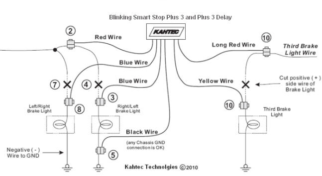
IV. Installation
|
Locate access to and identify the brake
light wires. The easiest way to access them is from
where you change the existing bulbs. Choose one side
(left or right) to start from.
Place a “Quick Connect” connector
over positive (+) side wire going to the first brake
light at least 3 inches from the light and insert the
short Red wire. Using the pliers, squeeze the metal
splice to secure the wires and then snap the cover
closed.
Place a second “Quick Connect”
connector over the same wire between the first one and
the brake light and insert the shorter Blue wire.
Squeeze and snap as in step 2.
Cut the positive (+) brake light wire
between the location of the 2 “Quick Connect”
connectors.
Place a “Quick Connect” connector
over negative (-) side wire of the brake light (or any
chassis “GND” connection) and insert the Black wire.
Squeeze and snap as in step 2.
Run the longer blue wire over to the
location of the other brake light.
Cut the positive (+) side wire of the
second brake light. Leave at least 2 inches.
Place a “Quick Connect” connector
over the exposed wire still attached to the light and
insert the blue wire. Squeeze and snap as in step 2.
Locate access to and identify the
third brake light wires.
Follow the instructions in steps 2,
3, and 4 for connecting to the third brake light using
the “long red” and yellow wires.
Secure the Smart Stop inside somewhere away from
areas of high temperature, moisture and water. |